Design 7 min read
Die cast aluminum enclosure: wall thickness, draft and sealing
By Inytialgo ·
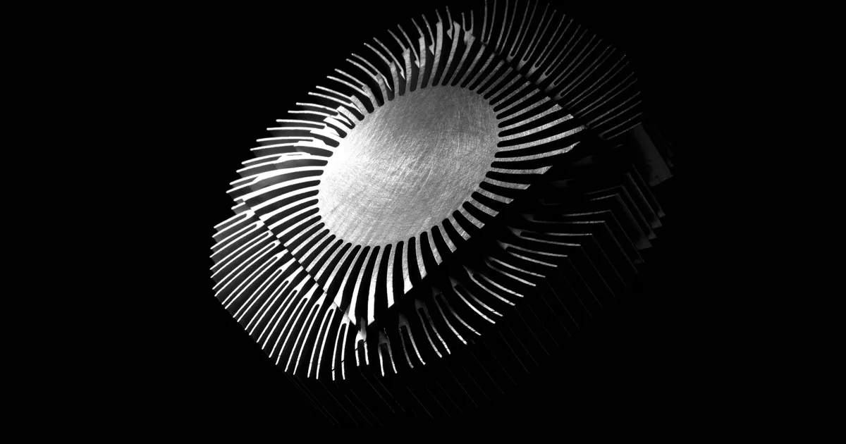
A die cast aluminum enclosure is a housing produced in one shot, with its walls, mounting bosses, ribs and sealing flange formed together in the steel. Its nominal wall usually lands around 3 mm, and that number is not a convention picked at random: it sits comfortably above the practical floor for aluminum high pressure die casting, and it is thick enough for a flange to stay flat, for a boss to hold a thread and for the box to survive being dropped on a plant floor.
Everything else in the design — draft, ribs, parting line, sealing, shielding — follows from two decisions taken early: how thick the wall is and where the die splits. Get those right and the enclosure is a cheap part. Get them wrong and you pay in slides, machining and leaks.
What is a die cast aluminum enclosure?
It is an electronics or instrument housing cast in aluminum rather than machined, extruded, folded from sheet or molded in plastic. It is chosen when a part has to do several jobs at once:
- Be stiff and take abuse, in outdoor, vehicle-mounted and industrial installations.
- Move heat out, using the housing itself as the thermal path, with cast fins where the dissipation justifies them.
- Contain and exclude interference, because a continuous metal box is an electromagnetic shield by construction.
- Carry its own features: bosses, gasket grooves, cable entries and mounting lugs cast in, rather than added afterwards.
Die cast aluminum enclosures show up in industrial control, instrumentation, telecom and outdoor radio equipment, sensors, lighting, and in equipment housings for medical devices, where a cleanable, rigid, shielded box is worth more than the tooling it costs.
The other casting route sometimes quoted for housings is investment casting. An investment cast enclosure buys finer detail and ferrous or stainless material options, at a slower process with a higher cost per part — a combination that rarely makes sense for an electronics housing in volume. Die casting for industrial enclosures wins on cycle time, thin uniform walls and cast-in features the moment quantities justify a die; investment casting keeps the niches where the material has to be steel or the volume never pays for the tooling.
If the choice between a metal and a plastic housing is still open, the material comparison is in die casting vs injection molding, and the alloy side of aluminum — A380, ADC12, AlSi9Cu3 — in aluminum die casting.
Why 3 mm is the wall thickness you keep seeing
Three millimeters is a compromise that works for most enclosure geometries, and it is worth understanding rather than copying.
- It clears the process floor with margin. Aluminum HPDC has a practical lower limit for a wall that has to fill completely and survive ejection. Sitting near that limit on a large flat panel means fighting cold shuts on every shot.
- It keeps the flange flat enough to seal. A gasketed lid needs a sealing face that does not bow between screws. Stiffness comes from thickness and from the flange geometry, not from tightening harder.
- It gives bosses something to live in. A boss standing on a thin wall drags the wall with it as it shrinks, and shows up as a sink mark or a crack.
Two clarifications that datasheets rarely spell out. The 3 mm figure is a nominal wall: the local thickness at bosses, ribs and the flange is deliberately different. And uniformity matters more than the number itself. An enclosure with a 3 mm wall and a 9 mm boss junction has a hot spot, and a hot spot solidifies last, which is where shrinkage porosity lives. Wherever the design forces a thick section, the way out is coring, blending the transition or reorganizing the geometry — never simply adding metal.
Ribs, bosses and cast-in features
Ribs are how a cast enclosure gets stiffness without gaining wall thickness. They work when they are thinner than the wall they support and generously radiused where they meet it; a rib as thick as the wall is just a mass that solidifies late.
Bosses follow the same logic. A cast, cored boss with a wall of its own beats a solid pillar of metal, and the fastening strategy has to be decided at the same time: thread-forming screws into a cast boss, a machined and tapped hole, or an insert. Each one implies a different boss diameter and a different tolerance, and each is far cheaper to choose now than to retrofit later.
Cable entries, mounting lugs, DIN-rail features and gasket grooves are all cheaper cast than machined — provided they sit on a face the die can open away from.
Draft, parting line and what the die can eject
Every wall parallel to the direction the die opens needs taper, and enclosures have a lot of those: four side walls, every boss, every rib and every internal pocket. Deep internal walls need more draft than shallow ones, and the surfaces that wrap a core need more than the ones that sit in the cavity. The full criterion is in draft angle in die casting.
The parting line is the other early decision. It determines which features can be cast directly and which need a slide — a side connector opening, a lateral mounting boss, an undercut lip. Slides are not forbidden; they are just a recurring cost in tooling, cycle time and maintenance, and they leave witness lines exactly where a gasket may want to run. Enclosures that are designed parting-line-first tend to need very few of them.
Sealing and ingress protection
Sealing a cast enclosure is a mechanical problem, not a material one. The gasket needs a continuous groove, a flange flat enough to compress it evenly and a screw pattern close enough that the lid does not lift between fixings. Cast surfaces have their own flatness behavior, so a demanding seal usually means machining the sealing face after casting — which is a decision to take while the die is being designed, because it changes the stock left on that face.
What earns the ingress rating is the assembly: groove, gasket, fastener pattern and cable glands together. The casting makes it possible; it does not deliver it on its own.
Shielding, finishes and grounding
A continuous aluminum box attenuates electromagnetic interference by construction, and then the design gives most of it back through openings, seams and finishes. Apertures — display windows, vents, connector cut-outs — are what leak, so their size and placement matter more than the wall thickness. Joints matter too: shielding depends on electrical continuity across the lid-to-body interface, which is why conductive gaskets and clean, unpainted contact areas exist.
Finish is the trap. Anodising builds an oxide layer that is an electrical insulator, so an anodised enclosure needs designated conductive areas — typically a conversion coating — wherever grounding or shielding continuity is required. Deciding the finish late, after the die is cut, is how a shielded design quietly stops being one.
What to check before committing steel
Before the tooling is quoted, five questions save the most money:
- Is the nominal wall uniform, and where are the unavoidable thick sections?
- Where does the die part, and how many slides does that choice imply?
- Which faces will be machined after casting, and is there stock for them?
- What is the fastening and sealing strategy, in that order?
- Does anything need electrical continuity, and does the finish allow it?
None of these is exotic. What makes them expensive is answering them after the steel is machined, when every change is a tooling modification instead of a line on a drawing.
Where to start
The fastest way to de-risk an enclosure is to look at how it fills and how it cools before the die exists: where the last metal arrives on a large flat wall, where the air ends up, and which boss junction solidifies last. That is exactly what the simulation software we distribute is for, and it keeps the analysis inside your own team.
If you already have an enclosure in production that is leaking, warping or scrapping at a specific boss, our consulting starts from that part and from the process as it actually runs.
- #die cast aluminum enclosure
- #wall thickness
- #EMI shielding
- #sealing
- #design
Found this useful? Add Inytialgo as a preferred source and you'll see our posts more often in your Google Search.
Add as a preferred source on Google