Dies 7 min read
Draft angle in die casting: what it is and how much you need
By Inytialgo ·
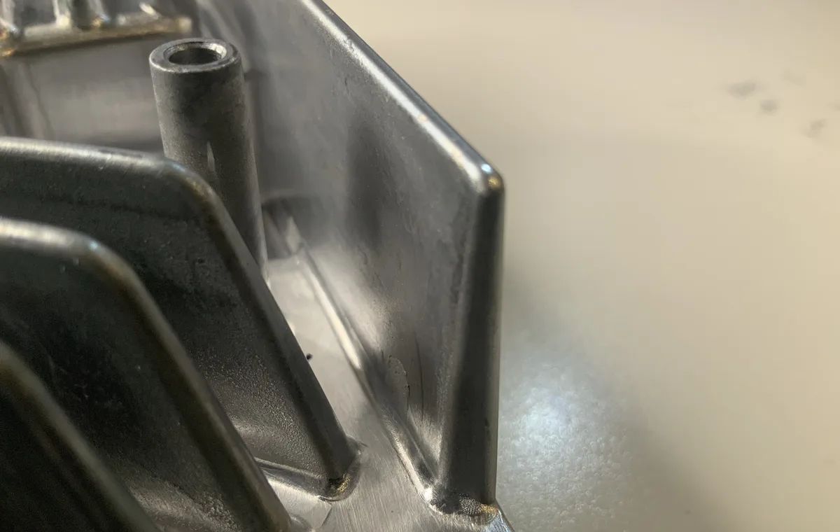
A draft angle is the taper given to every surface that runs parallel to the direction the die opens, so the casting can leave the steel without dragging against it. It is not a styling detail and it is not a safety margin: without draft, the part and the die are two interlocking pieces of metal, and something has to give.
The number itself is never universal. Draft depends on the alloy, on how deep the surface is, on whether it wraps a core or sits in the cavity, and on the surface finish you asked for — which is why “we always use one degree” is the most expensive default in tooling.
What is a draft angle?
Draft is the angle between a vertical wall of the part and the direction of die opening. Give a wall draft and it releases progressively as the die separates; give it none and the wall stays in full contact with the steel for the entire stroke.
The reason it matters more in metal than most people expect is thermal. The casting solidifies and then keeps shrinking as it cools, so it pulls away from the outer cavity walls and clamps down onto anything it surrounds. By the time the die opens, the part is not sitting loose in a box — it is gripping the steel. Draft is what turns that grip into a controlled release.
Why die casting draft is not injection molding draft
Most published draft angle guidance online is written for plastic injection molding, and it does not transfer cleanly. The geometry question looks identical; the physics behind it is not.
- The part is stiffer. A polymer part can flex its way out of a marginal wall. An aluminum casting does not flex — it scores, distorts or cracks.
- The tool runs hot and cycles hard. Die casting dies live under thermal fatigue and metal pressure. A wall that drags is not only a part problem, it accelerates soldering and wear on the steel.
- Ejection loads are far higher. The forces needed to break a casting free are what size the ejector system, and marginal draft raises them everywhere at once.
- The release agent is part of the system. Die lubricant helps, but it is a process variable, not a substitute for geometry — the day the spray drifts, an under-drafted wall is the first thing to fail.
The two processes also differ in where the standards live. In North America, die casting draft is tabulated in the NADCA product specification standards for die castings, which is what most prints and supplier quotes are referring to when they call a value “standard”. Injection molding guidance published for polymers is a different document for a different material, and quoting one on a casting drawing is a genuine source of argument between customer and foundry. The wider comparison between the two processes is covered in die casting vs injection molding.
What sets the requirement
There is no single draft angle for die casting because four things move it, and they move it independently:
- Inside or outside. Surfaces formed by a core need more draft than surfaces formed by the cavity, because the part shrinks onto the core and away from the cavity. This is the single most common thing missed on a first drawing.
- Depth of the surface. A shallow rib and a deep cored hole are not the same problem, and the published tables treat them separately. Do not scale one from the other by intuition.
- Alloy. Zinc, aluminum and magnesium are tabulated as different families. They shrink differently and they behave differently against the steel, so a value carried over from a zinc part is not automatically valid on an aluminum one.
- Surface finish and texture. A textured surface needs draft beyond the base requirement, because the texture itself is an undercut in miniature. The deeper the texture, the more it costs in taper.
The practical consequence: draft is read from the standard for the alloy and the depth in question, not chosen once and applied to the whole model. When a drawing carries a single blanket note, someone is going to discover the exception at tryout.
What happens when there is not enough draft
The failure is rarely dramatic on the first shot. It shows up as a slow tax on the program:
- Drag marks and scoring down the walls that had to slide out under pressure — cosmetic rejects on visible faces, and stress raisers everywhere else.
- Distortion at ejection. The pins have to overcome the grip, and the part bends around them instead of releasing. That is also where a part comes out looking fine and shows a fine crack at dimensional inspection two hours later.
- Ejector pin marks that get deeper over time, because the required force keeps climbing as the surface wears.
- Soldering and accelerated die wear, since the same faces are being scrubbed every cycle.
- Cycle time. A cell that fights ejection needs longer dwell, more spray or an operator intervening — and all three are paid for every shift.
None of these announce themselves as a draft problem. They arrive labelled as a process problem, and get chased with parameters for months. If the part is already in production and the defect always lands in the same place, geometry is usually a better first suspect than the machine — a pattern we describe in how the die casting process works.
What if a face cannot have draft?
Some faces genuinely cannot be tapered: a sealing surface, a bearing fit, a datum the customer will not move. There are three honest answers, and each has a price:
- Add machining stock. Cast the face with draft and machine it flat afterwards. The cheapest fix in tooling, the most expensive per part.
- Move the parting line or use a slide. Reorient the feature so it releases in a different direction. This buys the geometry and pays in die complexity, maintenance and cycle time.
- Redraw the feature. Often the requirement is inherited rather than functional, and the drawing simply never asked whether the zero-draft face needs to be zero-draft.
What does not work is leaving it on the print and hoping the foundry absorbs it. The die gets built, the part drags, and the discussion restarts with the steel already machined.
Where draft actually gets decided
Draft belongs to the part model, not to the die. That is an unpopular boundary because it means the decision happens before the tool shop is involved — while the geometry is still a CAD file and a change costs a line on a drawing.
The reliable sequence is this: apply draft to the model per the standard for the alloy and the depth, agree the direction of die opening before anything is detailed, and check the surfaces that a core will form separately from the ones the cavity will form. Then, when the filling and solidification are simulated, you are validating a part that can actually be ejected rather than one that merely fills well. A part with a perfect fill and marginal draft is still a program that fights you every shift.
One honest limit: draft does not compensate for a wall thickness that was wrong in the first place, and it does not rescue a part conceived for another process. It removes one specific, entirely avoidable reason for a casting to fail on its way out of the die. Which alloy family you are ejecting also changes the conversation, and the aluminum side of it is covered in aluminum die casting.
If the part is still a model, running the ejection and thermal picture in casting simulation software is the cheapest place to find the face that will drag. If the die already exists and a part is coming out marked every shift, our die casting consulting starts from that part on the bench.
- #draft angle
- #die design
- #ejection
- #tooling
- #HPDC
Found this useful? Add Inytialgo as a preferred source and you'll see our posts more often in your Google Search.
Add as a preferred source on Google