The full case
The problem: a thin part with a 0.1 mm flatness requirement
The customer had to develop a thin-walled die cast part with a flatness requirement of 0.1 mm. Unsure whether they could hold that tolerance, they paid close attention to everything that could distort the part.
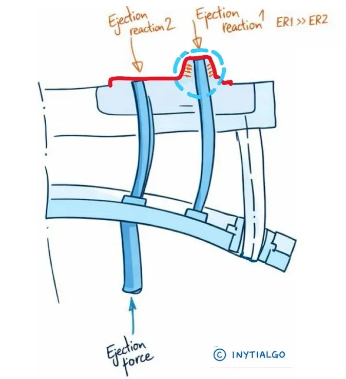
At INYTIALGO we saw the stiffness and stability of the ejection system as central to reaching that goal. Reviewing the customer’s design, we found a structural weakness that could set off a vicious circle: the lack of stiffness made the ejector pins lose parallelism as they moved, which encouraged binding and raised the force needed to eject the part. That extra force meant higher stresses on the part and, in the end, distortion.
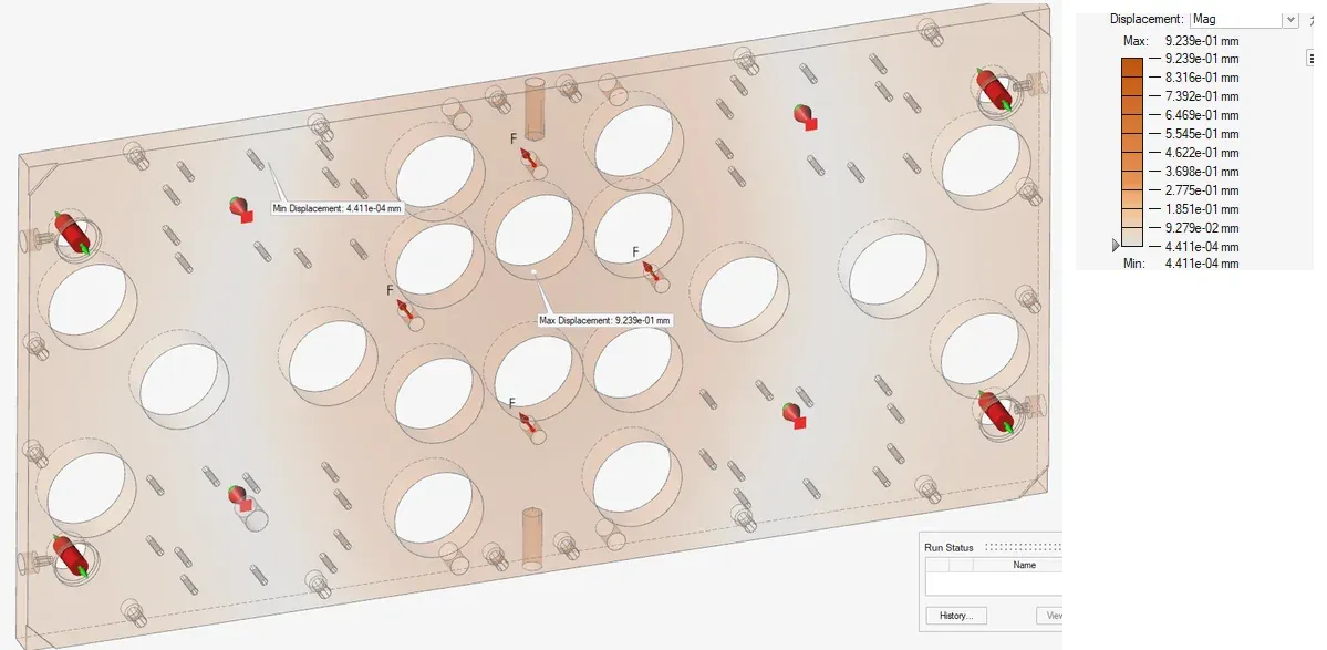
Using numerical analysis in Simcenter Simsolid (formerly Altair SimSolid), we were able to show the customer how their ejection system behaved and make that lack of stiffness visible. The analysis revealed deflections of up to 0.9 mm in the ejector plate, which made it clear the design had to be revised.
The speed of the tool meant the analysis could be done without the pre-processing that traditional methods require, and the visual display of the deformation made the problem easy to understand.
The solution: a stiffer plate and stable guiding
There are some common beliefs about what keeps an ejection system moving forward evenly and square. One of them is the mistaken idea that the longer the guided length of the ejector pins in their insert bores, the better the guiding, with no difference in travel between different points of the plate.
The ejector (knock-out) rods that connect the machine’s ejection to the die’s ejector plate also need to be put in perspective. Their layout does affect how the load is transmitted, but they contribute little if the assembly lacks the necessary stiffness and guiding.
At INYTIALGO we proposed a solution based on two key elements: the stiffness of the ejector plate and the stability of the guiding system. Both had to work together to keep the plate parallel as it advances, and to stop the ejector pins from taking on a guiding role that is not theirs.
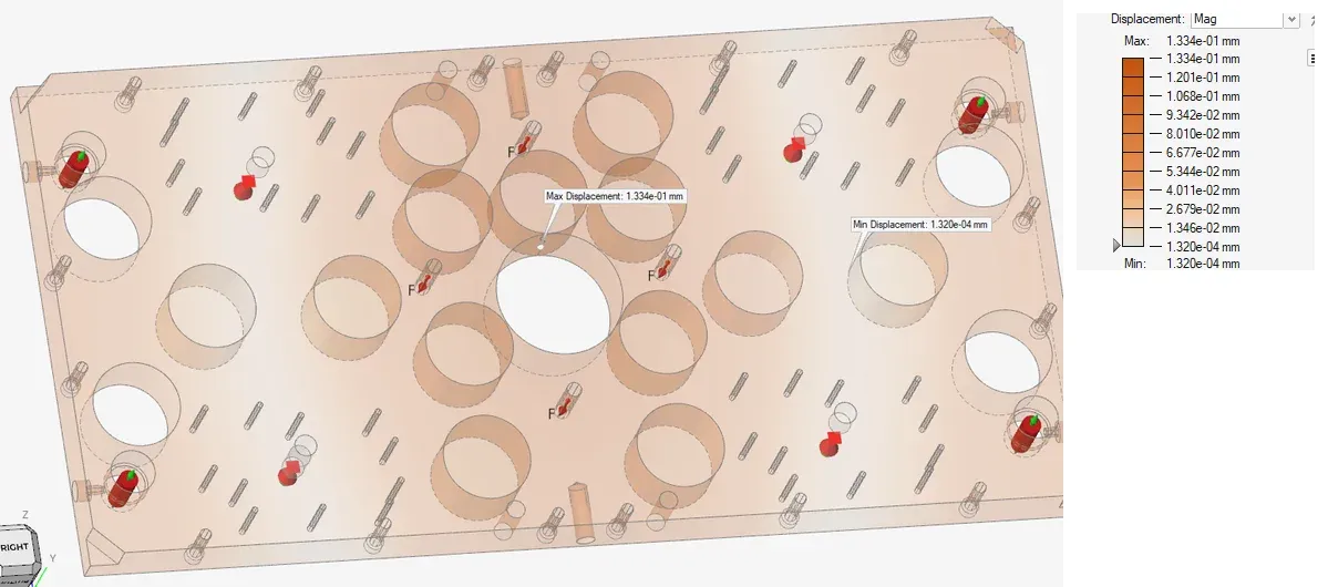
Once the changes were in the design, we analyzed the new concept again in Simcenter Simsolid. The results showed an ejector plate deflection about 7 times lower than in the original design: from 0.92 mm down to 0.13 mm.
The analysis quantified the stiffness gained by revising the ejector plate and its guiding system.
The results: ejection that no longer distorts the part
The real goal was a part that does not distort as it is released from the die. The best evidence that it was reached is the force needed to eject the same part: after the changes it dropped from 8 to 3 tonnes, a 62.5% reduction.
That difference led us to conclude that the lack of stiffness created extra friction, which amplified the ejection loads at the points of greatest adhesion. The uneven distribution of those loads, inherent to the part’s geometry and its release conditions, was made worse by the deformation of the system itself, and passed on to the part.
Part distortion does not come from ejection alone: it can also come from residual stresses or shrinkage. Even so, a robust, reliable ejection system minimizes the contribution of this stage and gives more stable, repeatable behavior, with less dependence on factors that are inherently variable, such as die lubrication. That makes residual distortion easier to control and allows it to be corrected with simpler procedures, for example during trimming.
Understanding ejection loads
To get to the root of ejection loads, it helps to separate the factors the die caster can act on, such as lubrication or certain aspects of die design, from those set by the part design. The latter include the part’s rib structure and the limits its geometry places on where and how ejector pins can be distributed.
These conditions reinforce the need for an ejection system stiff enough to transmit the required force without adding stresses that encourage the part to distort.
More on these factors can be found in INYTIALGO’s Technical guide to the design of thin-walled high-pressure die casting (HPDC) components.
On the blog, on the same subject: die cast tooling and designing die cast aluminum enclosures.
A recommendation for process control
Add ejection pressure to your statistical process control (SPC) parameters. On thin parts with tight flatness requirements, it is a particularly useful indicator for spotting changes in release conditions, excessive loads and the risk of distortion or breakage.
Setting a validated working range and tracking how it evolves lets you catch deviations and act before they turn into defects.
Keep the size of the available forces in mind: on the machine in this case, with 500 tonnes of clamping force, ejection capacity is 5% of it, which means up to 25 tonnes of force on the set of ejector pins. Check the actual capacity in the specifications of each machine.
- #ejection
- #ejector pins
- #die casting ejector pins
- #thin wall
- #flatness
- #SimSolid
- #HPDC
- #thixomolding